
Page 8 - 033
P. 8
VESSEL IMPACT ANALYSIS FOR RISER PROTECTION FRAME AND 7
PROTECTION NET SUPPORTS ON SEMI-SUBMERSIBLE OFFSHORE STRUCTURES
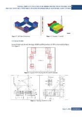
Figure 3. Hull Main Dimensions Figure 4. Computer FE model
3.1 Layout Details
Layout details and relevant drawings of RPF and PN structures of CPF are shown from Figure
5 to Figure 9.
Figure 5. Layout of CPF showing the RPF and PN structure
Figure 6. Drawing of RPF-01 of CPF
Sayı 3, 2015 GiDB|DERGi