
Page 31 - 07
P. 31
INTERCEPTOR DESIGN AND CONTROL FOR THE HIGH SPEED CRAFT 29
In Figure 5.4 the upper row which includes the comparison element, the control element, the
correction element and the process is the forward path, and the bottom row which includes the
measurement element is the feedback path. [17]
5.3 Digital and Analog I/O
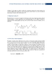
Basically there are two types of signals for both inputs and outputs, digital and analog. Digital
signals are either 1 or 0 (e.g. depending on the input/output type; 5V or 0V, HIGH or LOW) not
anything between. Analog signal can be any value in between these values for example, 2.3V or
4.56V etc.
Figure 5.5 Analog and digital signals from different sources [19]
5.4 PWM (Pulse Width Modulation)
To mimic an analog output which drives the actuator to 30 mm for example, instead of initial
point 0 mm and the utmost point of 50 mm (which is also the stroke length) digital output signal
is not sufficient since it is only HIGH or LOW, 1 or 0, 5V or 0V. First option to drive the
actuator to 30 mm length is to adjust the voltage as 3 volts, but with 3V the actuator will not
have the sufficient torque to actuate the designated load at the designated speed. To drive the
actuator on 30 mm length without the torque loss one should create an analog output but with
the maximum power, the best option is PWM (Pulse Width Modulation). PWM signals can be
simply explained as follows; during constant periods, “on” signal is given for a time (which is
referred as the pulse width), and then “off” signal until next period. Duty cycle is proportional
with pulse width which can be formulated as below. [20]
= 100% (4.1)
Sayı 7, 2016 GiDB|DERGi