
Page 15 - 033
P. 15
14 Ö. ÖZGÜÇ
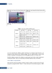
Figure 34. Load Case–03 for PN-02 Structure (PN- Figure 35. Load Case–04 for PN-02 Structure (PN-
02_LC03) 02_LC04)
Figure 36. Load Case–05 for PN-02 Structure (PN-
02_LC05)
Table 5. Load cases of RPF and PN Structures.
Structure Load Cases Load Cases Load Cases
RPF-01_LC01 RPF-01_LC02 RPF-01_LC03
RPF-01 RPF-01_LC04 RPF-01_LC05 RPF-01_LC06
RPF-01_LC07
RPF-02 RPF-02_LC01 RPF-02_LC02 RPF-02_LC03
RPF-02_LC04 RPF-02_LC05
PN-01_LC01 PN-01_LC02 PN-01_LC03
PN-01 PN-01_LC04 PN-01_LC05 PN-01_LC06
PN-01_LC07
PN-02 PN-02_LC01 PN-02_LC02 PN-02_LC03
PN-02_LC04 PN-02_LC05
It is to be noted that the colliding vessel is assumed to be completely rigid structure i.e. no
absorption of any fraction of the collision energy. Thus the complete kinetic energy during
collision is assumed to be absorbed by the RPF/PN supports and the CPF column only.
In all the collision scenarios, the collision is a point-contact and not line-contact, which gives
conservative results. Thus it can be said that the obtained results are very conservative.
5. FE Collision Analysis Results
With described loads and boundary conditions collision analysis is performed for all the four
structures by using LS-DYNA. Table 6 ~ 9 show the results of the collision analysis on RPF-
GiDB|DERGi Sayı 3, 2015