
Page 17 - 033
P. 17
16 Ö. ÖZGÜÇ
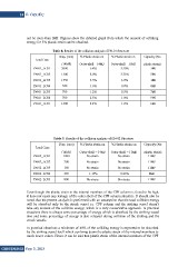
not be more than 3MJ. Figures show the detailed graph from which the amount of colliding
energy for 5% plastic strain can be obtained.
Table 8. Results of the collision analysis of PN-01 Structure
Load Case Disp. (mm) % Plastic strain on % Plastic strain on Capacity (No
PN-01_LC01
(14MJ) Outer-shell – 14MJ Outer-shell – 11MJ plastic strain)
2000 6.8% 3.50% 3MJ
5MJ
PN-01_LC02 1500 5.0% 3.75% 1MJ
4MJ
PN-01_LC03 1350 3.5% 1.0% 7MJ
9MJ
PN-01_LC04 520 1.6% 0.8% 6MJ
PN-01_LC05 700 1.2% 0.5%
PN-01_LC06 700 2.5% 1.0%
PN-01_LC07 1500 2.2% 1.2%
Table 9. Results of the collision analysis of PN-02 Structure
Load Case Disp. (mm) % Plastic strain on % Plastic strain on Capacity (No
PN-02_LC01
(14MJ) Outer-shell – 14MJ Outer-shell – 11MJ plastic strain)
1000 No strain No strain 11MJ
11MJ
PN-02_LC02 200 No strain No strain 11MJ
8MJ
PN-02_LC03 180 No strain No strain 11MJ
PN-02_LC04 420 1.15% 0.26%
PN-02_LC05 800 No strain No strain
Even though the plastic strain in the internal members of the CPF column is found to be high,
it does not cause any leakage of the outer shell of the CPF column structure. It should also be
noted that the present analysis is performed with an assumption that the total collision energy
will be absorbed only by the struck vessel i.e. CPF column and the striking vessel doesn’t
take any amount of the collision energy, which is a very conservative approach. In practical
situations there is always some percentage of energy which is absorbed by the striking vessel
also and some percentage of energy is also released during collision of the striking and the
struck vessels.
In practical situations a minimum of 40% of the colliding energy is expected to be absorbed
by the striking vessel itself which can bring down the plastic strain of the internal members to
much lower values. Hence it can be said that plastic strain of the internal members of the CPF
GiDB|DERGi Sayı 3, 2015