
Page 21 - 033
P. 21
20 Ö. ÖZGÜÇ
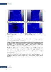
Figure 59. Strain distribution plot of CPF column Figure 60. Strain distribution plot of CPF column
externals for RPF02 (LC03)
externals for RPF02 (LC01)
Figure 61. Strain distribution plot of CPF column Figure 62. Strain distribution plot of CPF column
externals for PN01 (LC02) externals for PN01 (LC05)
6. Conclusion
Collision analysis of the riser protection frame (RPF) and protection net (PN) supports of
CPF is performed and presented in this paper.
Initially the collision analysis is performed with an objective of achieving zero plastic strain
on the CPF column structure that is supporting the RPF and PN supports but later it is
observed that it is very difficult to achieve it. Hence a plastic strain of 5% on the outer
shell of the CPF column structure is agreed to be acceptable.
The objective of this analysis is to avoid any kind of leakage into the CPF column due to the
collision, so it is important to control the plastic strain on the outer shell of the column.
Since the plastic strain of the internal members of the column, RPF and PN structures,
doesn’t cause any leakage inside the column, there is no criterion for the plastic strain of these
structural members.
Thus with the above collision energy and plastic strain criteria, the collision capacities of the
RPF and PN supports are estimated along the span of the structures for the given collision
energies.
GiDB|DERGi Sayı 3, 2015