
Page 19 - 033
P. 19
18 Ö. ÖZGÜÇ
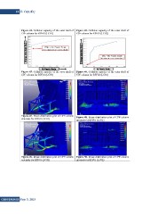
Figure 41. Collision capacity of the outer shell of Figure 42. Collision capacity of the outer shell of
CPF column for RPF01 (LC01) CPF column for RPF01 (LC02)
Figure 43. Collision capacity of the outer shell of Figure 44. Collision capacity of the outer shell of
CPF column for RPF01 (LC03) CPF column for RPF02 (LC01)
Figure 47. Stress distribution plot of CPF column Figure 48. Stress distribution plot of CPF column
externals for RPF01 (LC01) internals for RPF01 (LC01)
Figure 49. Stress distribution plot of CPF column Figure 50. Stress distribution plot of CPF column
externals for RPF01 (LC02) internals for RPF01 (LC02)
GiDB|DERGi Sayı 3, 2015