
Page 28 - 033
P. 28
EXPERIMENTAL INVESTIGATIONS OF 27
ACCELERATIONS AND VIBRATIONS ON VEHICLES AND BOATS
(3)
where VDV1 and VDV2 are the combined axis VDVs of trials 1 and 2, respectively, as given by
Equation 2. Since VDV is sensitive to both shocks and vibration, it is interesting to note the
estimated contribution to VDV of vibration alone, i.e., without the effects of impacts, and to
determine the dosage a person would have received had they been on the boat in calm water
with the engine running for the same length of time as the trials.
3. Experiment
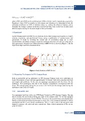
Inertial Measurement Unit (IMU) is an electronic device that measures and reports on a body’s
velocity, orientation, and gravitational forces, using a combination of accelerometers and
gyroscopes. It works by detecting the current rate of acceleration using one or more
accelerometers, and detects changes in rotational attributes like pitch, roll and yaw using one or
more gyroscopes. General view of Body Rotation of IMU Device is shown in Figure 1. All the
experiment steps have been discussed below.
Figure 1: Body Rotation of IMU Device
3.1 Measuring The Impacts On ITU Campus Roads
Both an automobile and an ambulance on ITU Ayazaga Campus roads were undertaken on
board. The duration of each trial was approximately 10 minutes. Both trials contained very hard
and rough road conditions. On the car, one passenger accompanied with the driver. On the
ambulance, three passengers, two was in the stretcher compartment, accompanied with the
driver. The average speed during the car cruise is 20.5 km/h and the average speed during the
ambulance cruise is the 25.9 km/h.
3.1.1 Automobile trial
Our experiment had done with a car (VW Passat Variant) on ITU Ayazaga Campus. The aim
was to measure the accelerations during the cruise on the campus roads. The car was equipped
with a tri-axial accelerometer (Xsens GT700). The axes of the accelerometer were aligned such
that the Z axis measured vertical acceleration or heave, the Y axis measured transverse or lateral
acceleration and the X axis fore-aft accelerations. The X, Y and Z axes of the rate gyros were
aligned to measure roll, pitch and yaw, respectively. Basic vehicle parameters of the car are
given in Table 1.
Sayı 3, 2015 GiDB|DERGi